|
project
isperom (more psi)
the story of project isperom
the 2003/2004 ford svt
mustang cobra has already etched its name �
terminator � into the history books as the
most powerful production mustang thus far.
with its base rating of 390 horsepower and 390
foot-pounds of torque, the eaton-supercharged,
cast-iron block, forged internal 4.6l is more
than an even mildly-unstable mustang
enthusiast could wish for from the factory.
throw in a heavy-duty t-56 transmission, a
3.55 gear ratio and some sinister good looks
and even the most hardcore tuners may be
satisfied. adding to its legacy, the
phenomenal handling right off the show-room
floor is eerily reminiscent of its venerable,
open-track-monster older-brother � the 2000
cobra r. with 600 pound per inch springs in
the front and rear, bilstein gas-charged
shocks and struts, beefed-up stabilizer bars,
2-piston 13 inch brembo brakes up front and an
8.8 inch independent rear suspension, the
similarities to its widely respected
predecessor are obvious. without a doubt, the
2003/2004 ford svt mustang cobra met and
exceeded the majority of the mustang-loving
population�s wildest expectations.
for some, however, the
2003/2004 terminator is merely a platform for
their dreams of a street-legal, daily-driver
super car. thanks to an aftermarket teeming
with a wide variety of well-manufactured
choices for various bolt-on modifications,
this sort of thing is well within nearly any
enthusiast�s grips. a high-performance muffler
system and an air intake put the vast majority
of �03/�04 cobras well into the 400 rear-wheel
horsepower realm. add a smaller supercharger
pulley and a custom tune and between 50 and 90
more rear-wheel horsepower can be had. for
those who want even more, bolt-on aftermarket
superchargers and nitrous oxide systems are
also readily available to catapult you into
the 500, 600, 700 rear-wheel horsepower
domains, within sight of the 800 rear-wheel
horsepower mark. these types of modifications
put the terminator on a road that very few
vehicles have ever traveled. but what happens
if that�s not quite enough?
it takes a different type
of human being to look at what most people see
as the pinnacle of high-horsepower setups and
say, �i want more.� there is one method of
forced induction that has no parasitic drag
and typically a much higher level of
efficiency: the turbocharger. amongst perhaps
the most significant reasons that most
cobra-owners shy away from the idea of a
turbocharged setup are the financial burden,
significant installation effort, supporting
modifications required and the fact that the
terminator comes with a supercharger from the
factory. but for those who simply want more,
the turbocharged route is the only option and
it is worth whatever it takes to get there.
one such person � jason
roth, of competition speed and sound, llc �
decided in april of 2005 that this was exactly
the destiny of his cobra. hearing about the
�typical� 600 rear-wheel horsepower
aftermarket-supercharged 2003/2004 cobras
ignited the desire for something different �
the road less traveled. he wanted to be able
to drive his vehicle to the local 1,320 ft.
runway, run mid 10s and drive home again while
still having the capability to go faster if
the need or desire so presented itself. for
jason, a person who�s had superchargers �
roots-style and centrifugal � and nitrous
oxide, there truly was only one form of
induction left in order to be taking on
something new and interesting. what better way
to learn more about how vehicles react to
different forms of induction and further one�s
own knowledge base? jokingly, the author of
this article believes that he merely has
supra-envy due to his southern florida
up-bringing and that he just needed a name
change on the various message forums he
frequents.
in all seriousness, it
takes a person very similar to jason �
technically, mechanically, and electrically
savvy � to undertake such a project, even with
some help. thankfully, there are even a good
number of choices for custom-fit turbocharger
systems for the 2003/2004 terminators. again,
taking the road less traveled, jason opted for
hellion power systems new
single turbonetics t76 (76mm ball-bearing)
turbocharger kit instead of a
twin-turbocharger setup. the reason�s he opted
for this kit are as follows:
- kit ships almost
immediately. no waiting months to receive
the kit
- top notch customer
service
- all stainless steel
piping
- no documented
installation problems
- when installed the kit
appears it could have come from the factory
- a single kit means
less parts to potentially have a problem
with and only 1 turbo to maintain
- the kit has been
proven at the track
this kit is rated to
support up to 950 crank horsepower and jason
intends to push the kit towards its maximum
horsepower rating. he intends to run
approximately 10 to 15-pounds on the street
and 20+ pounds at the drag strip, which should
put him in the 550-600 rwhp range on the
street and 700+ rwhp at the drag strip. with
more boost and other component changes the
900+ hp is well within reach. this setup
should satisfy the need for more power and
speed. at least we hope so�
the install
note: the following
are not step-by-step installation
instructions. this is to be used as reference
only based on our experiences during the
install. the installation of
hellion�s single-t76 turbocharger system �
assuming the right tools are at hand � is not
extremely complex or difficult. in fact,
installation is where the single-turbocharger
system may turn out to be quite advantageous,
when compared to some of the twin-turbocharger
setups available. the rest of this section
will be dedicated to a brief overview of the
steps that were taken to install the kit from
pulling the car into the bay and driving it
out.
suspension and chassis work
hellion�s single-turbocharger system
requires the removal and replacement of the
stock k-member, which cradles the engine in
between the front wheels. the granatelli or
upr k-member is standard in the kit to replace
the stock k-member.
maximum motorsports has also developed a
k-member that will fit and is offered as an
upgrade. the main reason the new k-member is
included in the kit is because of the
clearance requirements for the turbocharger
exhaust piping. the pa racing k-member will
also work with minor modifications to the
up-pipe. the d&d was installed by a customer
and apparently will work as well, but hellion
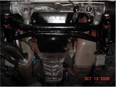
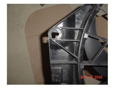
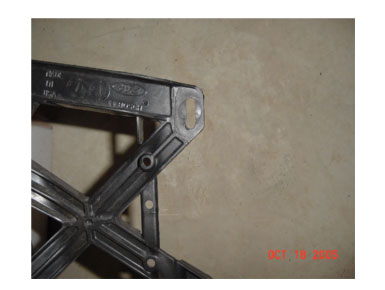
has not tested this on a vehicle. note: the
k-member in the picture is the incorrect
k-member for the
hellion turbo kit. granatelli drop
shipped the wrong one. the smaller bar that
angles back on both sides just behind the
larger bar should not be there. we had to cut
this off in order to make it work.
we
began the suspension and chassis work by
removing the rear springs and replacing them
with maximum motorsports coil-overs that had a
spring rate of 600-pounds per inch based on
maximum motorsports recommendation for a
daily driver/drag strip car. the rear coil-overs
are not required, but since the front
suspension would have coil-overs, jason saw
this as a perfect upgrade for performance and
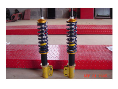
handling. the removal of the stock springs is
done with relative ease, as is the removal of
the factory bilstein shocks. the coil-overs
were assembled, put into place and quickly
adjusted to make them equal on both sides. the
following picture shows the assembled front
coil-over setup. the rears are very similar.
we
then proceeded to the front end of the cobra.
before we started on the
k-member, we determined that we couldn�t use
the 4-post lift to do the work because there
was no unobstructed way to support the engine
freely once it was detached from the k-member.
so, we decided to go the way of the floor jack
and jack-stands. the vehicle was placed on
jack stands on all 4 corners. we then used one
jack on the front of the transmission housing
and another on the front of the engine, using
a custom-cut piece of wood that fit snuggly
against the front of engine block on the front
of the oil pan lip to avoid putting pressure
on any engine components or brackets. there
are other ways to support the engine, but at
the time this proved to be the best
alternative with the hardware we had
available. once we were confident that the
engine was entirely supported on the jacks, we
removed the front wheels, brakes, rotors,
a-arms, springs, struts and began unbolting
the engine from the stock k-member. we
loosened all 4 front k-member bolts and 4-rear
bolts and then lifted the engine less than 1
inch with the jacks to allow for clearance
between the k-member and the engine. if you
have a firewall clutch adjuster, be sure to
screw it in as far as you can towards the
firewall. if not, the valve covers may
interfere with it and damage the adjuster when
jacking up the engine. after doing so, we
removed all the k-member bolts and dropped it
out. at this
point you need to remove the oil filter and
install the oil filter relocation adapter. if
you do not do this, it will be very difficult
and time consuming to remove the filter with
the k-member in place since the k-member will
hit the filter. if you are planning
on installing solid motor mounts, please do so
at this time. after setting the stocker aside
and grabbing the much-lighter granatelli
k-member and partially installing the bolts by
hand, the brake lines on the passenger side
need to be slightly pulled and bent forward
and the same on the driver side. there is a
grounding wire for the block that also gets in
the way of the k-member. relocate this ground
wire as necessary. we then squared the
k-member to the frame, bolted it up and then
tightened to spec. we then lowered the engine
back to its original position and tightened up
main engine mount nuts to spec.
next we installed the
tubular a-arms. again, follow the instructions
provided by the manufacturer here. we ran into
problems on the passenger side and believe the
a-arm mounting points were not welded in the
proper location. we had to trim the crushed
sleeve and one of the polyurethane bushings in
order to make the a-arm fit properly. the
problem location was the rear passenger-side
a-arm mount. after the a-arms were in-place
the install of the caster camber plates and
putting the front coil-over system together
was next on the list. jason opted for the
maximum motorsports caster camber plates
to match the coil-over setup, adjustability
and quality of their parts. we then assembled
the front coil-over assembly and followed the
manufacturer�s installation instructions for
the proper spacer usage with the coil-overs. a
spring rate of 350-pounds per inch was
selected based on
maximum motorsports recommendation for a
daily driver/drag strip car. next, install the
steering rack, front brake components, sway
bar, coil-overs and bolt the tie rod ends to
the spindle. here we ran into another problem.
the front mounting bolt head on the passenger
side for the a-arm had to be trimmed due to it
interfering with the steering rack assembly.
after doing so, it fit well. some of these
problems may not occur with other k-members
and to date jason has installed a upr k-member
without any of these problems. our experience
and discussion with others is that no k-member
is a direct replacement and modifications are
typical when replacing the factory k-member.
granatelli was contacted in regards to this
and offered great customer service and was
willing to replace any parts needed.
after completing the
installation of the coil-over setup, adjust
them per the manufacturer�s recommendations
and have a 4-wheel alignment performed. jason
opted for the car to sit a little bit higher
than it did with his steeda springs for ride
quality and drag strip performance.
first thoughts of the
ride quality are overall good. bumps are felt
a little more, but not too bad. this is
probably due to the spring rates selected. the
handling has been greatly improved. jason
noticed a binding noise when turning the wheel
to the left or turning left. after further
inspection and removal of the left coil-over
setup, the spring was rubbing on the inside
fender well. there is a cutout on the inside
driver fender well that has some metal that
protrudes towards the coil-over setup. the
spring was close enough that it would rub
depending on the rotation of the spring. this
protruding metal was grinded down to allow
clearance for the springs. depending on the
alignment, this may or may not be an issue for
others.
engine work
after
doing the necessary suspension and chassis
work, it was time to start on the
engine-related work. the first job tackled was
the installation of the oil filter relocation
kit. note: this should be done when doing
the k-member. the front bumper was removed
to make the installation of the kit easier.
the kit requires drilling two or three
(depending on relocation kit) holes in the
back of your front bumper, which turns out to
be not so easy. the metal for the bumper is
very thick and takes a while to get through,
even using a smaller bit to start it off. make
sure you are using a quality metal drill bit;
this will make it much easier and faster.
after drilling the holes, simply bolt up the
oil filter housing to the bumper and screw the
relocation adapter onto the oil cooler at the original
filter location on the engine block. press in
the supplied socketless straight barb fittings
to the socketless hose. cut the hose to the
proper length making sure no mechanical parts,
such as the sway bar will interfere with the
hose. once the hose is cut to length, press in
the other fittings and connect them to the
adapter that was just placed on the oil
cooler. we found putting the socketless hose
in boiling water for a couple of minutes
helped with the installation of the fittings.
see installation instructions for any other
specifics.
next the supercharger and
stock intercooler assembly, lower pulley and
all other idler brackets and pulleys
associated with the factory supercharger setup
were removed. the factory alternator is also
removed and replaced with a 99-01 cobra
alternator and put into the 99-01 cobra
alternator location. we highly recommend using
an egr blocking plate and cap on the exhaust.
this will eliminate the possibility of melting
through vacuum lines, wire harnesses and the
aggravation of the installation, all of which
we experienced. the factory power steering
fluid reservoir bracket is also replaced with
the 99-01 bracket and is provided with this
kit.
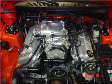
next the 99-01 cobra
upper intake and lower intake manifold was
installed. the installation also requires the
99-01 cobra throttle cable and the throttle
cable bracket. the alternator was then
installed with the coolant crossover tube at
the same time. this may take a few tries as
our first attempt resulted in the alternator
pulley hitting the crossover tube. the
solution to this was to put a couple of
washers under the crossover tube bolts to
raise it up a little bit, but not too high.
you need to make sure that the o-rings on the
crossover tube seal in the block. the 99-01
alternator requires the installation of a ford
pigtail harness, which wires into the existing
alternator harness, but requires one
additional wire that should be connected to
12-volts. we opted to connect this to the
same location that the battery is connected to
on the relay box in front of the driver side
strut tower. follow the
hellion instructions for the most part
with the rest of the installation.
other items of note are
the sensors. there are a few on the side of
the stock supercharger that are removed and
not used. the two that remain in use are the
iat2 (intake air temp 2)/map sensor and the
frps (fuel rail pressure sensor). this is
nice because it cleans up the driver side of
the engine bay considerably. what we decided
to do was put a vacuum hose on the driver side
port of the 99-01 intake that was large enough
to fit the iat2/map sensor inside so that it
can sense vacuum and temperature. another item
of note is the tps (throttle position sensor)
has to be reversed from the factory location
due to interference with the 99-01 upper
intake manifold.
the instructions state to
bend the power steering line that is mounted
on the reservoir bracket towards the engine.
i bent it towards the front of the reservoir
instead. this seemed to work better. final
step for the conversion was to install the
serpentine belt.
intercooler plumbing and exhaust tubing
work
note:
do not tighten any nuts and bolts until
everything has been assembled and fitted loose
first.
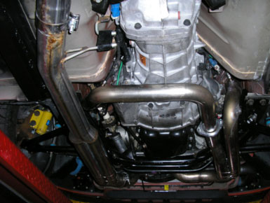
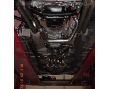
after all the engine work
was done, the plumbing for the up-pipe and
crossover tube with reducer (when using stock
exhaust manifolds) was installed. first the
exhaust was disconnected from the mid-pipe and
the mid-pipe removed from the exhaust
manifolds. be sure to unplug all of the o2
sensors prior to unbolting the mid-pipe. the
following picture was taken from under the car
after all of the exhaust tubing was installed.
it shows the crossover pipe and the up-pipe
that attaches to the passenger side exhaust
manifold and then bends down and under the
k-member to go to the front of the car and up
between the fan and engine. it also shows the
double barrel pipe that connects to the down
pipe from the turbo on one end and the mini
y-pipe on the other end where you can insert a
high-flow catalytic converter.
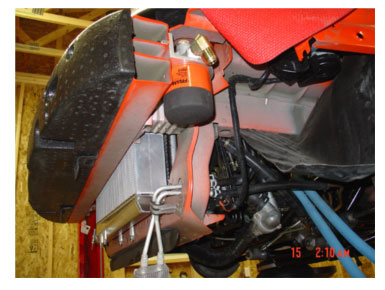
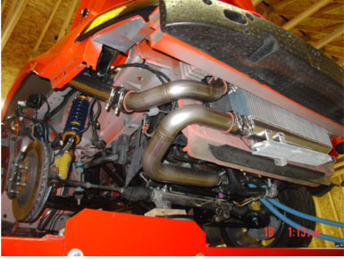
next the air-to-air
intercooler and associated piping was
installed. i have the original intercooler
that is angled. follow the
hellion installation instructions for
moving the appropriate wire harnesses and
electrical box in the passenger side fender
well. there are four mounting tabs on the
intercooler. the rear two were used to secure
the intercooler to the radiator support and
the front two i opted to cut off to allow the
power steering cooler to rotate up closer to
the intercooler. you can see the front two
mounting tabs in the picture prior to them
being trimmed. the intercooler piping was put
in place, but not tightened down until later
in the installation.
setup the turbo with the
vacuum line fitting, oil drain fitting and oil
feed fitting. make sure you use thread paste
for the oil drain billet aluminum fitting.
loosen the bolts on both the compressor and
exhaust side of the turbo in order to properly
clock it based on the instructions.
these should remain loose while it is
temporarily bolted up to the up-pipe. be sure
you bolt up the turbo bracket to the passenger
side valve cover and turbo, but do not tighten
the bolts at this time. this will help with
the proper clocking and alignment of the
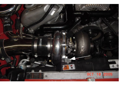
turbo. check the plugs on the fan to make sure
they do not interfere with the turbo. you may
need to make some adjustments and shift the
turbo in order to clear the plugs. i removed
the lower electrical plug that is attached to
the fan and positioned it out of the way. the
plug on the top of the fan shroud should be
between the compressor and center section of
the turbo as seen in the picture with the
white arrow. in my case, to be sure i had
proper clearance i went a little farther and
removed the fan and drilled out the mounting
holes on both sides as seen in the following
pictures to increase the clearance. this may
not be required for every install, but i found
that it helped with the overall alignment in
my situation.
the down-pipe was then
installed and mounted to the turbo. be sure
the clamp and down-pipe are aligned
correctly. follow the instructions for the
wastegate mounting. on the side that does not
use a gasket, you may opt to use high
temperature rtv. if you are planning on
installing a boost controller at the same time
as the turbo kit install or later date, i
highly recommend installing the hose barb
fitting and running a vacuum line from the
additional port on the wastegate and tie wrap
the vacuum line to a safe location. it is ok
that the vacuum line is venting to the
atmosphere. access to the wastegate is very
tight and this could save time later on.
during the install it does help to have the
coolant reservoir removed to assist with extra
space. after the wastegate is installed and
tightened and the turbo is properly clocked,
tighten a few of the bolts on the compressor
and exhaust side of the turbo. loosen the
down-pipe and remove the turbo. tighten
remaining bolts that were loosened to clock
turbo except for the two that will be
tightened later for the bracket to the
passenger side head. reinstall the turbo and
use the provided gasket and put the nuts and
bolts into the up-pipe hand tight, but do not
tighten them until the down-pipe and the bolts
for the reinforcement bracket to the passenger
side valve cover have been started. tighten
the downpipe to the turbo and be sure to check
for proper alignment. then tighten the four
bolts holding the turbo to the up-pipe and the
reinforcement bracket bolts on the turbo and
valve cover. finally, bolt up the double
barrel exhaust pipe, high-flow cat or
four-inch diameter straight pipe and shorty
y-pipe. be sure to use the supplied u-clamp
for the slip connection from the wastegate to
the downpipe. finally, tighten all bolts and
clamps on the exhaust side. the previous
picture shows the underside of the car looking
from the front to back. you can see the
crossover pipe, double barrel pipe, straight
pipe and y-pipe back into the catback.
after all of
the hot side (exhaust) piping was installed
and tightened down, the filter, mass air meter
and 4-inch intake tube were connected to the
compressor inlet side of the turbo. at this
time you can orientate all of the intercooler
piping and tighten the clamps at the polished
compressor-housing outlet side. also, tighten
the clamps for the piping at the intercooler
inlet that come from the polished
compressor-housing side of the turbo. next,
install the s-shaped intake tube in the
throttle body coupler and coupler coming
through the passenger side fender well.
install the small silicone coupler on the race
bypass blow off valve and position the blow
off valve and install it on the s-shaped
intake tube with the silicone coupler linking
the blow off valve and 4-inch inlet pipe that
has the maf and filter attached to it. once
all of these parts are in the proper position,
tighten the clamps for the s-shaped intake
pipe, silicone coupler on the blow of
valve/4-inch intake pipe and the hex set
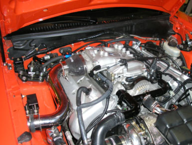
screws for the blow off valve. the intercooler
outlet piping clamps can now be tightened
down. be sure that both clamps are inside the
engine bay at the passenger side fender well
connection. the following picture is of the
engine bay showing the piping in-place.
the results
to date the car has been
put on the dyno twice. both have been
dynojets, however they have been at two
different speed shops. the first shop the car
was dyno�ed with the 0.81 a/r and the second
shop it was dyno�ed with the 0.96 a/r. the
outside temps and humidity were different, so
unfortunately i am unable to really compare
the two exhaust housings. however, from the
knowledge of others and turbonetics, the
larger exhaust housing would change the spool
up time and should increase power and torque
as well in the upper rpm ranges. my
experiences are that it takes approximately
200-300 rpm more to spool, which is hardly
noticeable and it does hold power higher in
the rpm range. it appears to make more
horsepower and hold it and appears to hold the
torque a little longer with less of a drop off
than with the 0.81 a/r exhaust housing. the
following graphs are from a dyno day we had at
johnny lightning performance in feb. 06�.
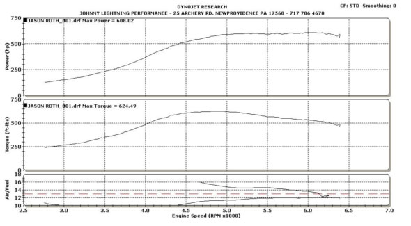
the following was with
15# of boost. the reason for the a/f reading
looking wacky is that the sensor blew out of
the tailpipe.
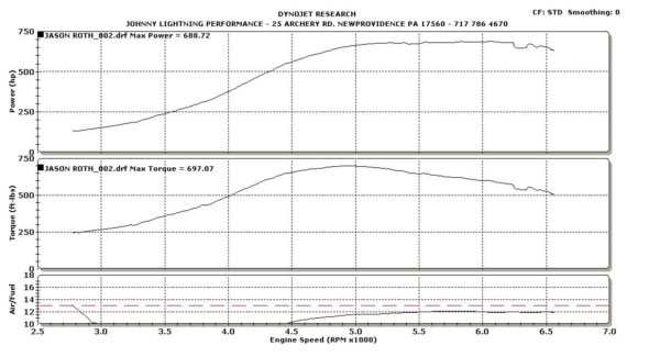
the following graph
was with 18#:
the final graph is
with 20.7#:
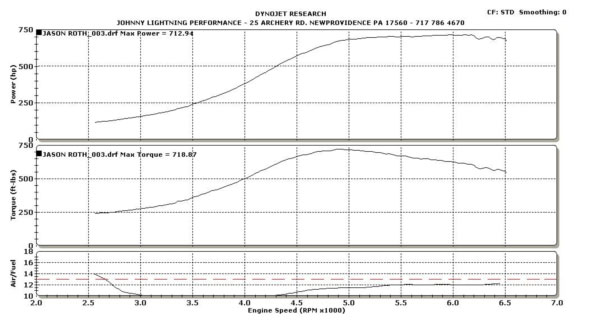
the car has not been
pushed over this amount of boost on the dyno.
i do not feel the need to max out the turbo
system for the sake of numbers. my goal for
the dyno is to determine the differences
between modification changes and for fun with
other car enthusiasts. the kit has made up to
847 rwhp in new mexico on another 03/04 cobra
at approximately 25# of boost.
there are now multiple
hellion 03/04 cobra�s running around the
united states and so far none have had
installation issues and have been basic bolt
on kits for those with many years of mechanic
experience and those with very minimal
experience. with no cutting required, basic
tools, customer service and the kits shipping
within days of ordering, this kit is by far
one of the best out on the market for proven
performance, reliability and cost. it is very
easy to duplicate the tuning and installation
with this kit. my tuner is jon lund of
lund racing and now has the same kit on
his car. the best my car has gone is 10.49 @
137.64 on 21.5# of boost. the car weighs
3900# with driver. at that mph with a better
60-foot it should go 10.20�s to 10.30�s at
that weight.
i am now in the process
of learning how to launch and get out of the
hole better with a turbo and manual
transmission. this is not an easy thing to do
with a turbo car and manual transmission. we
are changing things around with the tune,
2-step and timing retard.
please contact myself
(jason) with any questions you may have
regarding purchase, installation or general
questions about the kit and my experiences.
special thanks goes to
sean martin (blk03svtcobra) for the assistance
with writing this article.
|